AI-Generated Architecture Diagrams
Overview
Pidima's AI can automatically generate architecture diagrams from your requirements. Instead of manually writing PlantUML code, let AI analyze your requirements and create appropriate, well-structured diagrams for you.
How AI Generation Works
The Process
- Select Requirements — Choose which requirements to analyze
- Configure Generation — Select diagram type and options
- AI Analysis — AI reads and understands your requirements
- Diagram Generation — AI creates PlantUML code
- Automatic Rendering — Pidima renders the diagram image
- Review & Refine — Edit the generated diagram if needed
What AI Considers
- Requirement descriptions — Main content and details
- Requirement types — Functional, non-functional, constraints
- Requirement relationships — Dependencies and links
- Document context — Attached documents (if selected)
- System description — Your custom system overview
- Existing components — Previously defined actors and components
Generating Architecture Diagrams
Step 1: Access Generation
From Architecture Page
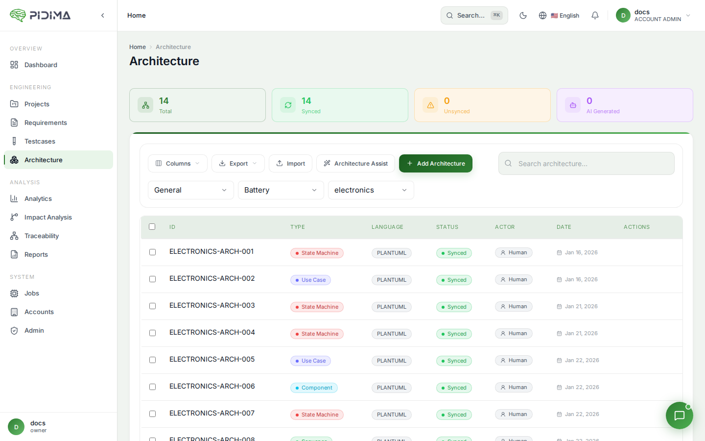
- Navigate to Architecture in your project
- Click Generate with AI button
- The generation dialog opens
From Requirements Page
- Select requirements you want to analyze
- Click Architecture Assist button
- Choose Generate Diagram
Step 2: Select Requirements
You have multiple ways to select requirements:
Manual Selection
- Click checkboxes next to specific requirements
- Use Select All to include all requirements in current view
- Selected requirements appear highlighted
Filtered Selection
- Apply filters (level, status, priority, type)
- Use search to find specific requirements
- Select all filtered results
Bulk Selection
- Select All — Includes all matching requirements
- Exclude — Remove specific items from "select all"
- Respects your active filters and search terms
Tip: For best results, select 5-15 related requirements. Too few may lack context; too many may create overly complex diagrams.
Step 3: Choose Diagram Type
Select the diagram type that best fits your needs:
Use Case Diagram
Best for:
- User stories and epics
- Functional requirements
- Actor interactions
AI will identify:
- Actors (users, systems, roles)
- Use cases (actions, features)
- System boundaries
- Relationships
Example: Requirements about user login, profile management, and authentication will generate a diagram showing User and Admin actors with their respective use cases.
Component Diagram
Best for:
- System architecture requirements
- Module and service definitions
- Integration requirements
AI will identify:
- Components (services, modules)
- Interfaces and APIs
- Dependencies
- Packages and subsystems
Example: Requirements about API gateway, authentication service, and database will generate a component diagram showing their relationships.
Sequence Diagram
Best for:
- Process flows
- API interactions
- Step-by-step procedures
AI will identify:
- Participants (actors, systems, services)
- Message sequences
- Time ordering
- Conditional flows
Example: Requirements describing a checkout process will generate a sequence showing the user, frontend, backend, and payment service interactions.
State Machine Diagram
Best for:
- Status workflows
- Object lifecycles
- State transitions
AI will identify:
- States (statuses, modes)
- Transitions (events, triggers)
- Initial and final states
- Guard conditions
Example: Requirements about requirement approval workflow will generate states like Draft, In Review, Approved, Rejected.
Class Diagram
Best for:
- Data models
- Object structures
- Entity relationships
AI will identify:
- Classes (entities, objects)
- Attributes (properties)
- Methods (operations)
- Relationships (associations, inheritance)
Example: Requirements about data structures will generate classes with their properties and relationships.
Step 4: Configure Generation Options
System Description (Recommended)
Provide context about your system to help AI generate better diagrams:
Example for a Medical Device:
Cloud-based medical device software for patient monitoring.
Uses embedded Linux system with:
- Qt-based user interface
- C++ backend services
- SQLite local database
- HTTPS communication with hospital server
- Compliant with IEC 62304
Example for an E-commerce Platform:
Microservices-based e-commerce platform.
Architecture includes:
- React web frontend
- Node.js API gateway
- Java Spring Boot services
- PostgreSQL database
- Redis cache
- Deployed on Kubernetes
Why it helps:
- AI understands your technology stack
- Generates more accurate component names
- Uses appropriate architectural patterns
- Aligns with your actual system
Actors (For Sequence Diagrams)
Specify actors/components that should appear:
Example for authentication flow:
User, Frontend, API Gateway, Auth Service, Database
Tips:
- List actors in typical interaction order
- Use consistent naming with your system
- Include external systems if relevant
- AI will use these and may add more if needed
Class Diagram Reference (For Sequence Diagrams)
Upload or reference an existing class diagram to help AI:
- Understand your data model
- Use correct class names
- Reference appropriate methods
- Maintain consistency
Document Context
Include attached documents in AI analysis:
- Enable Use Document Context toggle
- AI will analyze attached specifications, designs, etc.
- Provides richer context for diagram generation
Best for:
- Requirements imported from documents
- Complex specifications
- Detailed technical designs
Step 5: Start Generation
- Review all selections and options
- Click Generate Architecture Diagram
- An async job starts in the background
- You'll see a job notification
Generation time: Typically 30-90 seconds depending on:
- Number of requirements selected
- Diagram complexity
- Document context size
- AI model speed
Step 6: Monitor Progress
Job Status
- Click the Jobs icon (🔔) in the top right
- Find your architecture generation job
- Status shows:
PENDING→PROCESSING→COMPLETED
Notifications
- Success: "Architecture diagram generated successfully"
- Failure: Error message with details
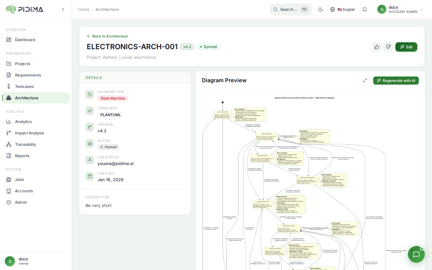
Step 7: Review Generated Diagram
Once complete:
- Navigate to the Architecture page
- Find your new diagram (usually at the top)
- Click to open and review
Check:
- ✅ Diagram renders correctly
- ✅ Elements match your requirements
- ✅ Relationships are accurate
- ✅ Naming is consistent
- ✅ Layout is readable
Step 8: Refine if Needed
AI does a great job, but you may want to adjust:
Edit PlantUML Code
- Click Edit on the diagram
- Modify the generated PlantUML code
- Click Preview to see changes
- Save when satisfied
Common Refinements
- Adjust layout direction
- Rename elements for consistency
- Add or remove relationships
- Simplify overly complex diagrams
- Add colors or styling
Regenerate with Different Settings
If the diagram isn't quite right:
- Delete the generated diagram (or keep for reference)
- Start a new generation with:
- Different requirements selected
- Modified system description
- Different diagram type
- Additional context
Advanced Techniques
Iterative Refinement
Technique: Generate multiple diagrams at different levels of detail
- High-level — Select epic-level requirements
- Mid-level — Select feature-level requirements
- Detailed — Select implementation requirements
Each provides a different view of your architecture.
Component Reuse
Technique: Build a library of components across diagrams
- Generate first diagram
- AI extracts and stores components (actors, services)
- Future generations reuse these components
- Maintains naming consistency
Example:
- First diagram identifies: "User", "API Gateway", "Auth Service"
- Second diagram automatically reuses these names
- Consistency across all architecture documentation
Context Layering
Technique: Provide increasingly specific context
Layer 1: System Description
E-commerce platform using microservices
Layer 2: Technology Stack
E-commerce platform using:
- React frontend, Node.js BFF, Java services
- PostgreSQL database, Redis cache
- Kubernetes on AWS
Layer 3: Specific Services
Services include:
- Product Catalog Service
- Order Service
- Payment Service
- Notification Service
- User Service
More context = more accurate diagrams.
Document-Driven Generation
Technique: Use architectural decision records (ADRs) or design documents
- Attach design document to requirements
- Enable document context in generation
- AI reads both requirements and design docs
- Generates diagram aligned with documented decisions
Best Practices
Selecting Requirements
Do:
- ✅ Select related requirements (same feature/component)
- ✅ Include 5-15 requirements for balance
- ✅ Mix different requirement levels for depth
- ✅ Apply filters before selecting
Don't:
- ❌ Select hundreds of requirements (too complex)
- ❌ Mix unrelated features (confusing diagram)
- ❌ Include only one requirement (lacking context)
Providing Context
Do:
- ✅ Describe your actual technology stack
- ✅ List real service/component names
- ✅ Mention architectural patterns used
- ✅ Be specific and accurate
Don't:
- ❌ Leave system description empty
- ❌ Provide generic or vague descriptions
- ❌ Contradict your actual architecture
- ❌ Include irrelevant information
Choosing Diagram Types
Do:
- ✅ Match diagram type to requirement nature
- ✅ Generate multiple types for different views
- ✅ Use sequence diagrams for flows
- ✅ Use component diagrams for structure
Don't:
- ❌ Force requirements into wrong diagram type
- ❌ Try to show everything in one diagram
- ❌ Generate same type repeatedly without reason
After Generation
Do:
- ✅ Review and verify accuracy
- ✅ Link diagram to source requirements
- ✅ Add assumptions if needed
- ✅ Refine layout and styling
Don't:
- ❌ Accept without reviewing
- ❌ Ignore obvious errors
- ❌ Leave unlinked to requirements
- ❌ Generate and forget
Troubleshooting
Diagram Too Complex
Problem: Too many elements, hard to read
Solutions:
- Select fewer requirements (5-10 instead of 20+)
- Break into multiple focused diagrams
- Use filters to narrow scope
- Generate separate diagrams per subsystem
Missing Key Elements
Problem: AI didn't include important components
Solutions:
- Add system description with component list
- Specify actors explicitly
- Provide document context
- Edit diagram manually to add missing pieces
Inconsistent Naming
Problem: Components named differently than your system
Solutions:
- Update system description with exact names
- Build component library by saving custom components
- Edit diagram to match your conventions
- Regenerate with corrected context
Generation Failed
Problem: Job completes with error
Solutions:
- Check that requirements have descriptions
- Verify requirements are accessible
- Reduce number of requirements
- Try different diagram type
- Check system logs or contact support
AI Generation Tips
Get Better Results
- Write clear requirements — AI uses requirement text, so clear descriptions generate better diagrams
- Use consistent terminology — Same terms across requirements = coherent diagrams
- Provide examples — System description with examples helps AI understand your patterns
- Start simple — Generate simple diagrams first, then increase complexity
- Iterate — First generation may not be perfect; refine and regenerate
Understanding AI Decisions
AI makes these choices:
- Element naming — Based on requirement text and system description
- Relationships — Inferred from requirement dependencies and descriptions
- Layout — Optimized for readability
- Grouping — Logical subsystems based on context
If AI's choices don't match your intent, provide more specific context or edit the diagram.
Examples
Example 1: User Authentication Use Case
Selected Requirements:
- "User must be able to log in with email and password"
- "System shall support password reset via email"
- "Admin can manage user accounts"
System Description:
Web application with user authentication
Generated Diagram:
@startuml
left to right direction
actor "User" as user
actor "Admin" as admin

rectangle "Authentication System" {
  usecase "Login" as UC1
  usecase "Reset Password" as UC2
  usecase "Manage User Accounts" as UC3
}

user --> UC1
user --> UC2
admin --> UC3
@enduml
Example 2: API Gateway Component
Selected Requirements:
- "API Gateway shall route requests to appropriate services"
- "Authentication service validates JWT tokens"
- "All services connect to PostgreSQL database"
System Description:
Microservices architecture:
- API Gateway (routing)
- Auth Service (authentication)
- Business Service (core logic)
- PostgreSQL database
Generated Diagram:
@startuml
package "Services" {
  [API Gateway]
  [Auth Service]
  [Business Service]
}

database "PostgreSQL" {
  [Database]
}

[API Gateway] --> [Auth Service]
[API Gateway] --> [Business Service]
[Auth Service] --> [Database]
[Business Service] --> [Database]
@enduml
Example 3: Checkout Sequence
Selected Requirements:
- "User selects items and proceeds to checkout"
- "System validates inventory before payment"
- "Payment is processed through Stripe"
- "Order confirmation email is sent"
Actors Specified:
User, Frontend, API, Inventory Service, Payment Service, Email Service
Generated Diagram:
@startuml
actor User
participant Frontend
participant API
participant "Inventory Service" as Inventory
participant "Payment Service" as Payment
participant "Email Service" as Email

User -> Frontend: Checkout
Frontend -> API: Submit Order
API -> Inventory: Check Availability
Inventory --> API: Available
API -> Payment: Process Payment
Payment --> API: Success
API -> Email: Send Confirmation
Email --> User: Confirmation Email
API --> Frontend: Order Complete
Frontend --> User: Success Message
@enduml