Creating Architecture Diagrams
Overview
This guide walks you through creating architecture diagrams in Pidima, both manually and through AI assistance. You'll learn how to write PlantUML code, preview diagrams, and manage your architecture documentation.
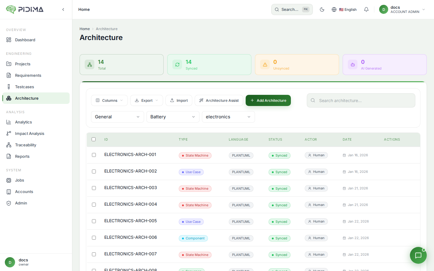
Accessing Architecture Management
Navigate to Architecture
- Select your Organization from the dropdown
- Choose an Account
- Select a Project
- Click Architecture in the left sidebar
Level Selection
Architecture diagrams are organized by project levels. Select the appropriate level where you want to create your diagram.
Creating a New Diagram Manually
Step 1: Open Create Dialog
- Click the + Add Architecture button
- The architecture creation dialog appears
Step 2: Fill Basic Information
Diagram Name
Give your diagram a descriptive name:
✅ Good: "User Authentication Flow"
✅ Good: "Payment Processing Component Architecture"
❌ Bad: "Diagram 1"
❌ Bad: "Untitled"
Diagram Type
Select the appropriate diagram type:
- Use Case — User interactions and system boundaries
- Component — System components and their relationships
- Sequence — Time-ordered interactions between objects
- State Machine — State transitions and events
- Class Diagram — Object structure and relationships
- Custom — Any other PlantUML diagram type
Step 3: Write PlantUML Code
Use Case Diagram Example
@startuml
left to right direction
actor "User" as user
actor "Admin" as admin

rectangle "Pidima System" {
  usecase "Create Requirements" as UC1
  usecase "Generate Tests" as UC2
  usecase "Manage Users" as UC3
  usecase "View Reports" as UC4
}

user --> UC1
user --> UC2
user --> UC4
admin --> UC3
admin --> UC4
@enduml
Component Diagram Example
@startuml
package "Frontend" {
  [Web Application]
  [Mobile App]
}

package "Backend Services" {
  [API Gateway]
  [Requirements Service]
  [AI Service]
  [Auth Service]
}

database "PostgreSQL" {
  [Database]
}

[Web Application] --> [API Gateway]
[Mobile App] --> [API Gateway]
[API Gateway] --> [Requirements Service]
[API Gateway] --> [AI Service]
[API Gateway] --> [Auth Service]
[Requirements Service] --> [Database]
[Auth Service] --> [Database]
@enduml
Sequence Diagram Example
@startuml
actor User
participant "Web App" as Web
participant "API Gateway" as API
participant "AI Service" as AI
database Database

User -> Web: Request AI-generated test
Web -> API: POST /api/v1.0/testcases/generate
API -> Database: Fetch requirements
Database --> API: Requirements data
API -> AI: Generate test cases
AI --> API: Generated tests
API -> Database: Store test cases
Database --> API: Success
API --> Web: Job ID
Web --> User: Generation started
@enduml
State Machine Diagram Example
@startuml
[*] --> Draft

Draft --> InReview : Submit for review
InReview --> Approved : Approve
InReview --> Rejected : Reject
Rejected --> Draft : Revise
Approved --> Published : Publish
Published --> Archived : Archive

Archived --> [*]
@enduml
Class Diagram Example
@startuml
class Requirement {
  -UUID id
  -String name
  -String description
  -RequirementType type
  -Priority priority
  +create()
  +update()
  +delete()
}

class TestCase {
  -UUID id
  -String name
  -String steps
  -String expectedResult
  +execute()
  +link()
}

class Architecture {
  -UUID id
  -String name
  -String plantumlCode
  -DiagramType type
  +render()
  +validate()
}

Requirement "1" --> "*" TestCase : verifiedBy
Requirement "1" --> "*" Architecture : describedBy
@enduml
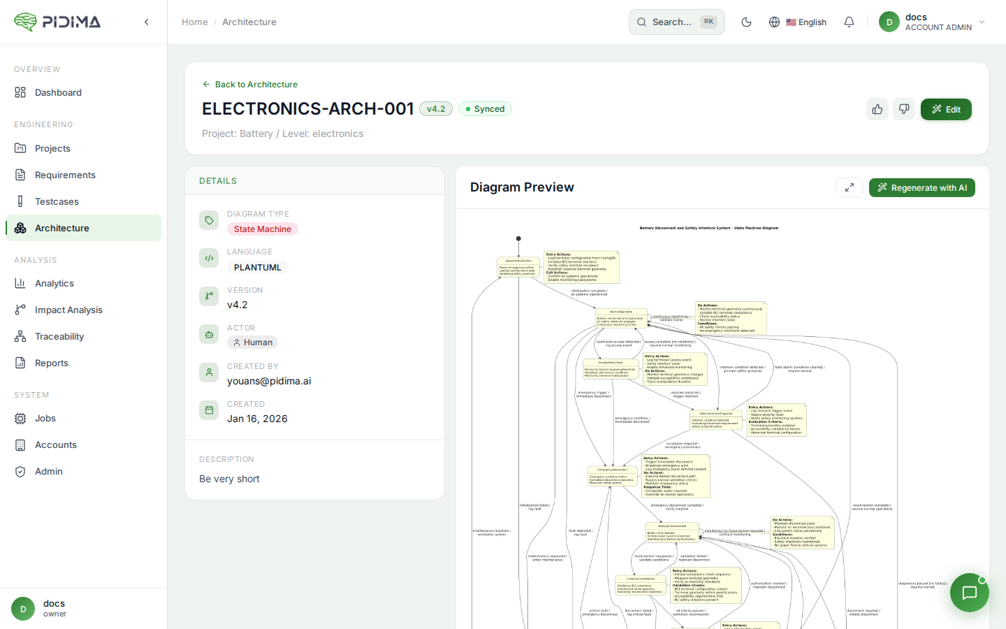
Step 4: Preview Your Diagram
- Click the Preview button to see your diagram rendered
- Make adjustments to the PlantUML code as needed
- Preview again to verify changes
Tips for Preview:
- Preview updates in real-time as you edit
- Check for syntax errors highlighted in red
- Verify that all elements are properly positioned
- Ensure text is readable at the rendered size
Step 5: Add Assumptions (Optional)
Document architectural assumptions or decisions:
Example Assumptions:
1. All API calls use JWT authentication
2. Database uses connection pooling (max 20 connections)
3. AI service has 5-second timeout
4. System supports up to 10,000 concurrent users
Assumptions help future maintainers understand:
- Why certain design choices were made
- What constraints were considered
- What conditions must remain true
Step 6: Save the Diagram
- Review all information
- Click Create to save your diagram
- The diagram appears in your architecture list
Editing Existing Diagrams
Open for Editing
- Find your diagram in the architecture list
- Click on the diagram name to open details
- Click Edit button
What You Can Edit
- Diagram name — Change the descriptive title
- PlantUML code — Modify the diagram structure
- Assumptions — Update architectural decisions
- Links — Add or remove requirement connections
Regenerating the Image
If you edit the PlantUML code:
- Click Regenerate Image to update the visual
- Wait for the rendering to complete
- The updated diagram appears
PlantUML Tips and Tricks
Basic Structure
Every PlantUML diagram starts with @startuml and ends with @enduml:
@startuml
' Your diagram code here
@enduml
Comments
Add comments to explain your diagram:
@startuml
' This is a single-line comment

/' This is a
   multi-line comment '/

actor User ' Inline comment
@enduml
Styling
Customize colors and appearance:
@startuml
skinparam backgroundColor #FEFEFE
skinparam componentStyle rectangle

component "API" <<REST>> #LightBlue
component "Database" <<PostgreSQL>> #LightGreen

API --> Database
@enduml
Layout Direction
Control diagram orientation:
@startuml
left to right direction
' or
top to bottom direction
@enduml
Grouping Elements
Group related elements:
@startuml
package "Backend Services" {
  [Service A]
  [Service B]
}

package "External Systems" {
  [Third Party API]
}
@enduml
Common Diagram Patterns
Microservices Architecture
@startuml
!define RECTANGLE rectangle
skinparam componentStyle rectangle

cloud "Internet" {
  [Load Balancer]
}

RECTANGLE "Kubernetes Cluster" {
  [API Gateway]
  [Auth Service]
  [Requirements Service]
  [AI Service]
  [Notification Service]
}

database "PostgreSQL" {
  [Primary DB]
  [Read Replica]
}

queue "Message Queue" {
  [RabbitMQ]
}

[Load Balancer] --> [API Gateway]
[API Gateway] --> [Auth Service]
[API Gateway] --> [Requirements Service]
[API Gateway] --> [AI Service]
[Requirements Service] --> [Primary DB]
[AI Service] --> [RabbitMQ]
[Notification Service] --> [RabbitMQ]
@enduml
API Request Flow
@startuml
participant Client
participant "API Gateway" as Gateway
participant "Auth Service" as Auth
participant "Business Service" as Business
database Database

Client -> Gateway: Request + Token
Gateway -> Auth: Validate Token
Auth --> Gateway: Valid

Gateway -> Business: Process Request
Business -> Database: Query Data
Database --> Business: Data
Business --> Gateway: Response
Gateway --> Client: Response

@enduml
State Management
@startuml
[*] --> Idle

Idle --> Loading : fetch()
Loading --> Success : data received
Loading --> Error : error occurred
Success --> Idle : reset()
Error --> Idle : retry()
Error --> Loading : automatic retry

Success --> [*] : cleanup()
@enduml
Validation and Best Practices
Diagram Validation
Pidima validates your PlantUML code:
- ✅ Syntax correct — Diagram renders successfully
- ⚠️ Syntax error — Invalid PlantUML code
- ⚠️ Empty diagram — No content to render
Keep Diagrams Simple
- Aim for 5-15 elements per diagram
- Break complex systems into multiple diagrams
- Focus on one aspect or layer at a time
Use Consistent Naming
- Match names to your requirements and code
- Use the same terminology across all diagrams
- Be consistent with capitalization and formatting
Add Context
- Include a descriptive diagram name
- Document assumptions and constraints
- Link to related requirements
Troubleshooting
Diagram Won't Render
Problem: Preview shows error Solutions:
- Check for missing
@startumlor@endumltags - Verify all parentheses and brackets match
- Remove special characters that might break syntax
- Try simplifying the diagram to isolate the issue
Elements Overlap
Problem: Diagram elements overlap or crowd together Solutions:
- Use
left to right directionortop to bottom direction - Add hidden arrows to control layout:
A -[hidden]-> B - Simplify the diagram and split into multiple diagrams
Text Too Small
Problem: Labels are hard to read Solutions:
- Shorten element names
- Use abbreviations consistently
- Split into multiple focused diagrams